


Manager Zhou
Leave a message
summary
◆ All parts are treated with hot-dip galvanizing for corrosion prevention. Hot dip galvanizing cannot guarantee the required rotation parts, and stainless steel materials are generally used. Fasteners below M8 are made of stainless steel, while the rest are hot-dip galvanized.
The conductive part of the copper tube is a soft connection type, with a "handshake" type self operated contact finger in the middle. The spring is externally pressed and no current passes through. The isolation switch only has one contact point in the middle, and the rest are fixed and connected with soft connections.
Adopting a new contact structure, fixing one end of the contact piece to the contact seat, and relying on the deformation of the contact piece and the contact pressure generated by the spring, the sliding contact at the end of the contact finger is changed to a fixed contact, improving the reliability of conductivity;
◇ Change the finger spring to an external type to avoid spring diversion;
Adding magnetic lock plates to improve dynamic and thermal stability performance.
The rotating part is equipped with a self-lubricating sleeve, which does not require lubricating grease.
The main wiring Terminal is a flat plate type. When the current level is 630A, tin plating is applied to the surface of conductive components; When the current level is 1250A-4000A, the surface of conductive components is silver plated.
The upper and lower caps of the ceramic parts are hot-dip galvanized for rust prevention, and ceramic parts with different climbing distances can be selected according to the different pollution levels in the region; During the production and manufacturing process, the creepage distance is designed to be higher than the standard value based on positive deviation control.
The switch post insulator has high strength density, stability and reliability. The formula is made of high-strength ceramic material, which reduces the dispersion of product strength and increases the tensile strength of the product. The structural design has already provided a large strength reserve for the product, ensuring stability and reliability during operation.
Structure Introduction
The 35kV complete set of isolation switches consists of GW4-40.5 (D) (W) type isolation switch body, CS11 or CS8-6D type manual operating mechanism, transmission accessories, etc. It can also be equipped with CJ6 type electric mechanism, etc. The 110kV complete set of isolation switches consists of GW4-126 (D) (W) type isolation switch body, CS14G manual operating mechanism, transmission accessories, etc. It can also be equipped with CJ6 type and other electric mechanisms.
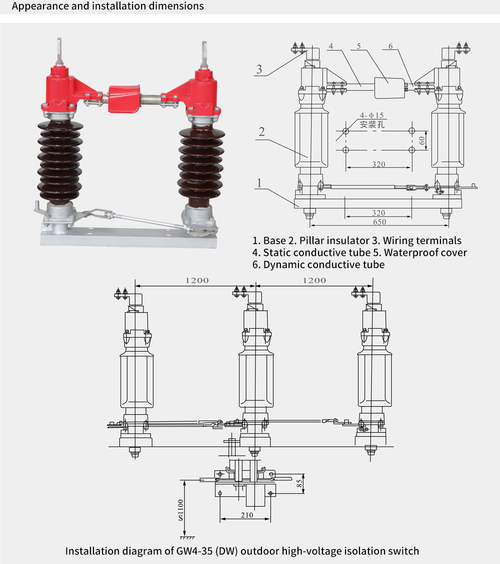
The isolation switch is a double column horizontal opening isolation switch. Make it into a single form, and when used synchronously, connect it with connecting rods. Each single-stage is composed of a base, post insulators, output sockets, and contacts. The two post insulators are installed parallel to each other on the bearings at both ends of the base and perpendicular to the base. The main electrical components are installed above the two pillar insulation porcelain bottles and rotate approximately 90 degrees with the pillar insulation porcelain bottles.
Each bearing seat of the isolation switch is equipped with a shaft assembly, and the two shaft assemblies are connected for transmission through connecting plates, adjusting screws, etc.
The copper braided strip in the outlet socket is flexibly connected to the conductive rod and the terminal block, and the terminal block is used for users to connect the circuit.
The contact fingers of the middle contact part are assembled in pairs, using self operated contact fingers in the form of a rotating type to reduce wear between the contacts and fingers during opening and closing, and improve service life.
When the isolation switch is equipped with a Grounding switch, the interlocking between the main electrical circuit and the grounding switch is ensured by the fan-shaped plate and arc-shaped plate on the base. When the main electrical circuit is closed, the grounding switch cannot be closed, and when the grounding switch is closed, the main electrical circuit cannot be closed. When using CS8-6D, the interlocking between the isolation switch and the grounding switch is achieved by the interlocking board on the mechanism.
Product Features
The isolation switch adopts a double column center opening and contact turning structure, which has the ability to automatically clean the contacts and improve contact reliability;
The touch finger is made of high-strength, high conductivity, and high elasticity materials. By relying on the elastic force of the contact fingers to clamp the contacts, the vicious cycle of reduced clamping force, increased contact resistance, and intensified contact heating caused by spring corrosion and thermal annealing is avoided;
The rotating part of the isolation switch is designed to be maintenance free. The rotating seat is designed with a sealed structure, which prevents water vapor, dust, and harmful gases from entering. This ensures that the bearings and lithium based grease of molybdenum disulfide work in a good environment, preventing the bearings from rusting, the grease from flowing out, and from drying up. As a result, the operating torque of the isolation switch will not increase after long-term operation. Adopting a structure that combines stainless steel shaft pins with oil-free self-lubricating shaft supports; The steel parts are hot-dip galvanized, and the isolation switch is flexible, lightweight, reliable, and rust free to operate.
Technical Parameter
| NO. | Item | Unit | Data | ||||
| 01 | rated voltage | kV | 40.5 | 72.5 | 126 | ||
| 02 | Rated Absolute Edge level | 1-minute power frequency withstand voltage | to ground | kV | 95 | 140 | 230 |
| fracture | kV | 115 | 160 | 245 | |||
| Lightning impulse withstand voltage (peak value) | to ground | kV | 185 | 325 | 550 | ||
| fracture | kV | 215 | 375 | 630 | |||
| 03 | Rated frequency | Hz | 50 | ||||
| 04 | Rated current | A | 400 630 1000 | 1250 1600 2000 | 3150 4000 | ||
| 05 | Rated short-time withstand current | kA | 20 2031.5 | 31.5 40 40 | 50 50 | ||
| 06 | Rated peak withstand current | kA | 4050 63 | 80100100 | 125 125 | ||
| 07 | Rated short-circuit duration main knife/ground knife | s | 4/2 | ||||
| 08 | Rated terminal Mechanical load | Horizontal and vertical loads | N | 750 | 1000
| ||
| Horizontal lateral load | N | 500 | 750 | ||||
| Vertical force | N | 750 | 1000 | ||||
| 09 | Creepage Distance | mm | 1025-1250 | 1800-2250 | 3150-3900 | ||
| 10 | mechanical life | times | 2000 | ||||
| 11 | Human operated mechanism | ungrounded | CS11(F) | ||||
| Single grounding | CS8-6D(F) | ||||||
| Single grounding | Main blade CS14G (F); Ground Knife CS11 (F) | ||||||
| Control circuit voltage | V | AC220,DC110,DC220 | |||||
| 12 | Electric motor operating mechanism | model | CJ6 | ||||
| Electric motor voltage | V | AC380 | |||||
| Control circuit voltage | V | AC220,AC380,DC220 | |||||
| Opening and closing time | s | 6±1 | |||||
| 13 | Product weight | ungrounded | kg | 360 | 500 | 700 | |
| Single grounding | kg | 410 | 600 | 800 | |||
| Double grounding | kg | 460 | 700 | 900 | |||


 RELATED
RELATED
RELATED
RELATED
RELATED
RELATED
RELATED


Oil&Gas exploited
Automotive Manufacturing
Transportation & Dlistrlbutlon
Manufacture
Industrial Construction
Green Energy
Copyright ? 2024 All Rights Reserved
Back to top 


Comment
(0)